The original post was so big that I split it up into two parts.
Continuing from last week’s post showing how to implement a “Chunky” fog of war, this week I will wrap-up the series by showing you how to implement a “Smooth” fog of war. Smooth is by-far my favorite because it yields much more natural-looking fog.
Smooth Fog
The implementation for smooth fog is similar to chunky. You still need a fog map (or fog data stored someplace) and a step to apply the shape, but there are other steps in the process that require extra effort. The result is a much smoother fog and it’s well worth the extra graphic space (and a small amount of data space) if your app can spare it.
Map Tiles: A Refresher
I am assuming you have read Part 1 of this series. If you haven’t yet, I recommend you do before continuing. However, in order to put all the information you need in one place, here is a section of that post:
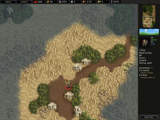
Fog of war systems are normally used in games that use a map to represent the level the units are traversing. For example, in the WarCraft II illustration at the top of the previous post, you can see that there are water and ground tiles. (There are also trees but they’re out-of-frame.) This map is usually an array of tile data (structures) that store information specific to that tile: the type of tile it is (water, grass, etc.), if a unit can walk on it (grass would be true, a tree would be false, for example), and so on.
Fog systems are the same way. They use the notion of tiles to represent how the fog looks and therefore go hand-in-hand with the normal tile map. This means that the size of the fog tile is usually the same size as the terrain tile. Therefore, you can take advantage of this idea and store the fog-specific information along with the normal tile data. If you want to keep the fog data separate from the normal data, you can certainly do that. You would just need to have another fog-specific map.
My fog tile map is an array of FoWEntry structures:
struct FoWEntry
{
    unsigned short  m_bits;
    // other data goes here
};
Sub-Pixels Described
The key to making the smooth fog system work is the notion of sub-pixels. In order to achieve a smooth fog, you have to define more than just “on-or-off”. You need to somehow ‘describe’ the amount of fog there is in each tile. An elegant way to do that is by defining sub-pixels.
A single bit represents each sub-pixel. The bit-numbering system starts with the upper-left sub-pixel and follows left-to-right top-to-bottom as shown below (you can define the sub-pixels however you wish of course):
![]()
As you can see, the system described here divides each pixel into 9 sub-pixels (3×3). You could divide it into 2×2 — and that would certainly be smoother than the chunky system — but for my needs I had enough space for a 3×3. Conversely, you can also define more than 3×3. The important thing to remember though is that the more bits you need, the bigger the lookup table needs to be. A 3×3 system needs 9 bits, which equates to a table with 512 entries. A 2×2 needs 4 bits, which is just 16 entries.
Step 1: Define Your Tiles and Lookup Table
The first step in using sub-pixels is to define your tiles. This is a two-pronged step. On the one side, you need to determine how many graphic tiles you want in your fog (more about this in a moment), and on the other, you need to determine which bits represent those tiles. Here are some examples:
![]()
In the above examples, you can see that the fog covers a certain area of each tile. In the first example, the coverage is about 50%. In the middle example, the coverage is about 33%, and so on. What your artist needs to determine is how much coverage there should be per tile. The easiest way to do that is for them to draw a circle on graph paper and see where the line falls and then make some generalizations. The amount of coverage you want to represent will determine how many graphic tiles your artist needs to create.
At first it might seem like a daunting task to define every permutation of bit definitions. You don’t. You only have to define the entries you care about. For example, I have no need (or desire) to show a tile that has all bits set except 4 (which looks like a doughnut). I also don’t care about a tile that only has bit 4 set. The bits you define are totally up to you, but know that you don’t have to crazy with them. I’ll show you in a moment that you don’t need a large number of them to get a smooth circle.
Bit Definitions Described
Let’s take a moment to talk about what I mean when I say “bit definitions”. Here is a specific example.
I know that I will want to represent corners. Which bits could I use to describe a northwest corner, for example? You could go with something like this:
![]()
Now that we have the definition, we need to determine where in the lookup table it resides. Here is an illustration that shows this:
![]()
You can see that the green bits are set and that in turn creates a hex value. In this case, it’s 0x5F (entry 95 in the table), so we set table entry 95 with the id of the graphic tile that represents the northwest corner. In my case, it’s a frame number, but for you it could be a file name to the specific .PNG file, or whatever suits your purpose.
Again, you need to repeat these steps only for the tiles you care about. So how do you define the tiles you don’t care about? That’s quite easy. For my system, I define -1 to mean ‘undefined’. If you were storing file names, a NULL/NIL would serve the same purpose. Using a definition such as this is also a good debugging tool. We’ll talk more about that in Step 4: Draw The Fog.
Here is how I initialize my lookup table:
signed char fow_frame_table[NUM_FOW_ENTRIES];

for (int i = 0; i < NUM_FOW_ENTRIES; i++)
{
    fog_frame_table[i]  = -1;
}
fog_frame_table[0x5F]   = 0;
fog_frame_table[0xB]    = 1;
fog_frame_table[0x7]    = 2;
...etc...
When you’re done defining all of your relevant entries, you’ll end up with a table that contains mostly -1’s, with ‘spot’ entries containing real data.
Step 2: Define Your Shape Masks
Now that you have all of your tiles defined, you’re able to define what I call the ‘circle masks‘. Where the Chunky system uses a real-time system of circle drawing and filling, the Smooth system does all of the heavy-lifting offline. That is, you define ahead of time the shape (and look) of the circle at each radius you want to support. We do that with masks.
Before we do that though, we need to first make maintenance easy on ourselves: we should define the bits with code. You can skip this step if you want, but I wouldn’t recommend it. It’s much easier to handle (and debug/modify) if you use something other than raw numbers.
First we to define our 9 bits:
#define FOW_BIT_NW  (1 << 0)
#define FOW_BIT_N   (1 << 1)
#define FOW_BIT_NE  (1 << 2)
#define FOW_BIT_W   (1 << 3)
#define FOW_BIT_C   (1 << 4)
#define FOW_BIT_E   (1 << 5)
#define FOW_BIT_SW  (1 << 6)
#define FOW_BIT_S   (1 << 7)
#define FOW_BIT_SE  (1 << 8)
Next, we need to use those bits to create masks that define the bit definitions we created in Step 1:
// these are all 7 chars to make it easier to read the circle masks
#define fow_non         0
#define fow_all         (FOW_BIT_NW | FOW_BIT_N | FOW_BIT_NE |
                         FOW_BIT_W | FOW_BIT_C | FOW_BIT_E |
                         FOW_BIT_SW | FOW_BIT_S | FOW_BIT_SE)

#define NUM_FOW_ENTRIES fow_all

// straights
#define fow_EEE         (FOW_BIT_SE | FOW_BIT_E | FOW_BIT_NE)
#define fow_NNN         (FOW_BIT_NE | FOW_BIT_N | FOW_BIT_NW)
#define fow_WWW         (FOW_BIT_NW | FOW_BIT_W | FOW_BIT_SW)
#define fow_SSS         (FOW_BIT_SW | FOW_BIT_S | FOW_BIT_SE)

// corners
#define fow_CNE         (FOW_BIT_E | FOW_BIT_NE | FOW_BIT_N |
                         FOW_BIT_NW | FOW_BIT_C | FOW_BIT_SE)
#define fow_CNW         (FOW_BIT_N | FOW_BIT_NW | FOW_BIT_W |
                         FOW_BIT_SW | FOW_BIT_C | FOW_BIT_NE)
#define fow_CSW         (FOW_BIT_W | FOW_BIT_SW | FOW_BIT_S |
                         FOW_BIT_NW | FOW_BIT_C | FOW_BIT_SE)
#define fow_CSE         (FOW_BIT_S | FOW_BIT_SE | FOW_BIT_E |
                         FOW_BIT_NE | FOW_BIT_C | FOW_BIT_SW)

// joins
#define fow_JNE         (FOW_BIT_E | FOW_BIT_NE | FOW_BIT_N)
#define fow_JNW         (FOW_BIT_N | FOW_BIT_NW | FOW_BIT_W)
#define fow_JSW         (FOW_BIT_W | FOW_BIT_SW | FOW_BIT_S)
#define fow_JSE         (FOW_BIT_S | FOW_BIT_SE | FOW_BIT_E)
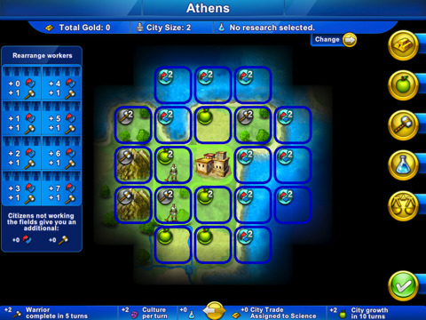
Notice that even though I have 9 bits at my disposal, I only care about 14 combinations of them. (By way of comparison, Civilization Revolution uses 80…that has really smooth fog!) Also notice that all of the defines have the same number of characters. This makes the circle easier to see. This is made even more readable by mixing upper- and lower-case.
Now you need to use the masks to create an array for each radius in your system. Here is my table for a circle with a radius of 3:
fow_all,fow_all,fow_CNW,fow_NNN,fow_CNE,fow_all,fow_all,
fow_all,fow_CNW,fow_JNW,fow_NON,fow_JNE,fow_CNE,fow_all,
fow_CNW,fow_JNW,fow_NON,fow_NON,fow_NON,fow_JNE,fow_CNE,
fow_WWW,fow_NON,fow_NON,fow_NON,fow_NON,fow_NON,fow_EEE,
fow_CSW,fow_JSW,fow_NON,fow_NON,fow_NON,fow_JSE,fow_CSE,
fow_all,fow_CSW,fow_JSW,fow_NON,fow_JSE,fow_CSE,fow_all,
fow_all,fow_all,fow_CSW,fow_SSS,fow_CSE,fow_all,fow_all,
The source code for the article defines radii 3-9. The way I determined the shape for all of them was to use the same circle draw routine that the chunky system used to get the basic shape, then I just smoothed it out in the corners by hand. You could also use any drawing program that has a circle tool. I liked the fine control I got my own circle draw routine so I was happy with that.
Step 3: Apply The Mask
With the masks defined, it’s important to know that these shape masks are fundamental to how the smoothing system works. The real magic happens when those masks are applied to the fog map. The process is very simple and straightforward, but it’s a powerful system and uses bits for what they were originally intended for: each entry in the shape mask array is bitwise ANDed with whatever data is already in the map. This system maintains the fog coverage bits and is the reason why merging more than one circle is always perfectly handled without resorting to ugly hacks and work-arounds.
Most of the work has already been done in the shape masks. The way I apply the shape mask is I first populate a local array (the same dimensions as the shape mask) with the tiles that were potentially affected, and then just do a one-to-one AND application. Like so:
#define FOW_RADIUS_MIN  3
#define FOW_RADIUS_MAX  9

void    fowCircleMidpoint(int   xCenter,
                          int   yCenter,
                          int   radius)
{
    BHLIB_DEBUG_ASSERT(radius >= FOW_RADIUS_MIN);
    BHLIB_DEBUG_ASSERT(radius <= FOW_RADIUS_MAX);

    {
        // populate the local array
        const int   length      = (radius * 2) + 1;
        const int   num_entries = length * length;

        FoWEntry *  fow_entry[num_entries];

        int tile_counter    = 0;
        for (int y = yCenter - (length / 2);
             y <= (yCenter + (length / 2));
             y++)
        {
            for (int x = xCenter - (length / 2);
                 x <= (xCenter + (length / 2));
                 x++)
            {
                fow_entry[tile_counter] = getFoWEntry(x, y);
                tile_counter++;
            }
        }

        // apply the mask
        const unsigned short *  mask    = &circle_mask[radius - FOW_RADIUS_MIN][0];

        for (int i = 0; i < num_entries; i++) { if (fow_entry[i]) { fow_entry[i]->m_bits    &= *mask;
            }

            mask++;
        }
    }
}

FoWEntry *  getFoWEntry(const int   tile_x,
                        const int   tile_y)
{

    {
        const int   map_tile_width  = m_map_width;
        const int   map_tile_height = m_map_height;

        if  (
                (tile_x < 0) ||
                (tile_y < 0) || (tile_x >= map_tile_width) ||
                (tile_y >= map_tile_height)
            )
        {
            return(NULL);
        }

        FoWEntry *  fow_entry   = m_fow_map;
        fow_entry   += ((tile_y * map_tile_width) + tile_x);

        return(fow_entry);
    }
}
Note that you need to make sure you don’t try to read or write outside of the fog map.
Step 4: Draw The Fog
Now you’re finally at the last step! Time to visualize the fog data. This step is even easier than applying the shape mask.
All you do is traverse the fog map and use the bits as a direct index in the tile definition table we created in Step 1.
void    renderFoW()
{
    {
        const int   map_tile_width  = m_map_width;
        const int   map_tile_height = m_map_height;

        FoWEntry *  fow_entry   = m_fow_map;

        for (int y = 0; y < map_tile_height; y++)
        {
            for (int x = 0; x < map_tile_width; x++) { if (fow_non != fow_entry->m_bits)
                {
                    if  (true == tile_is_onscreen)
                    {
                        BHLIB_DEBUG_ASSERT(0 == (fow_entry->m_bits & ~fow_all));
                        const int   frame_id    = m_fow_frame_table[fow_entry->m_bits];

                        #if defined(_DEBUG_BUILD)
                        if  (-1 == frame_id)
                        {
                            BHLIB_DEBUG_LOG_MESSAGE("unsupported table entry for: 0x%X\n", fow_entry->m_bits);
                        }
                        else
                        #endif
                        {
                            // draw the tile
                        }
                    }
                }

                fow_entry++;
            }
        }
    }
}
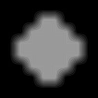
When you’re all done, you’ll see something like the following:
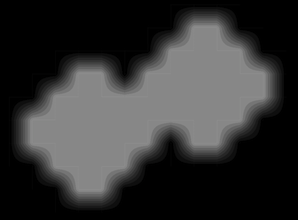
And as I mentioned earlier, it works perfectly when one light circle needs to merge with another. Here is an example of that:
Some optimizations that I have done in the rendering step is to not draw anything if there are no bits set. You could have defined this in your definitions but since there are no bits set, there shouldn’t be any pixels set either. You don’t need to waste time trying to draw something that is completely empty.
Another optimization is the ‘standard’ notion of not wasting time trying to draw something that is completely off-screen.
I wanted to point out the debugging information I mentioned in Step 1. At draw time, if I obtain a table entry that is -1 (or NULL/NIL) then I have made an error someplace. Usually it means I haven’t given the lookup table a valid entry and need to do so. I want to know which entry that is so I display a message to the console telling me that.
Whenever this debug message triggers, it usually means that I have come across a legal bit definition that I haven’t accounted for. This doesn’t mean I need to create a new graphic tile; I just need to tell the system what to draw in this case. I have to look at the bits and see what it looks like on paper before knowing what tile id resembles it the closest.
Get Creative With Your Fog
What’s great about this implementation is that it can be used for more than just traditional fog. Anything that can be revealed is a viable candidate: clouds, water, whatever. Get clever and take it in unexpected and fresh directions!
Here are some examples of fog of war systems used by other games:
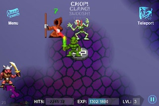
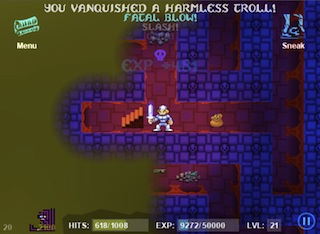
Both of the Fargoal games (Sword of Fargoal [iPhone] and Sword Of Fargoal Legends [iPhone/iPad Universal]) make great use of fog tiles:
It’s a little hard to see (it was the only screenshot I could find), but here is Civilization Revolution (iPhone/iPad):
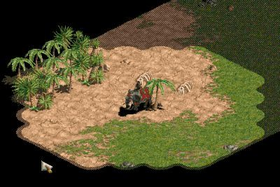
And here is an example from Age of Empires showing a fog system done with isometric tiles:
The Code
Here is a zip file of all the code files represented by the fog system I have described. I have even created the shape masks for all radii from 3 to 9 to get you started. Enjoy!
fog_code.zip (BSD License, use at your own risk)
Acknowledgments
I would like to thank Sam Nova and Noel Llopis for peer-reviewing this series. Thank you, guys!